Installation
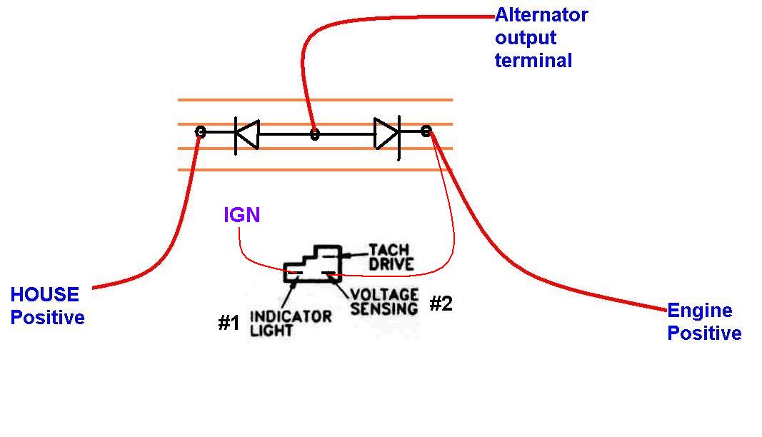
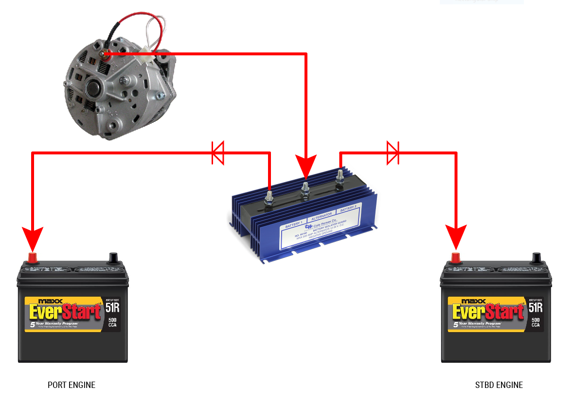
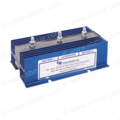
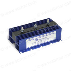
Diode battery isolators allow simultaneous charging of two or more batteries from one alternator, without connecting the batteries together. In a well-planned DC distribution system, it is always a good idea to keep the battery banks “isolated” so that the house bank cannot have an opportunity to “drag” down the engine batteries and leave you stranded. One thing to keep in mind when setting up a system with a battery diode isolator is that the alternator must have the ability to “sense” voltage from one of the battery banks. In the illustration below, the sensing lead from the alternator is connected to the engine “cranking” battery. The sensing lead is used to provide the alternator with real-time voltage so the regulator can determine whether or not to provide a charge. Another trick to setting up a well-planned system is to add a priority switch in the sensing lead circuit that will allow you to switch between sensing either the engine bank or the house bank of batteries so that you can apply charge to the batteries dynamically. Another tip is to mount the isolator vertically so it can better dissipate heat.
Sensing Issues with 1-wire Alternators
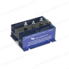
Some 1-wire “self exciting” alternators rely on a direct connection to the battery to sense and provide charge as they do not have a separate lead that can be connected to sense battery voltage. In this case a standard diode alternator will not work as the diode itself will block access to sense voltage from the batteries. In situations like this, it will be necessary to obtain a battery isolator that has a voltage output the alternator can sense… this is sometimes termed as a “Alternator energize input”. Diodes with an energize input feature a special current limited energize input that will power the B+ when the engine run/stop switch is closed.

